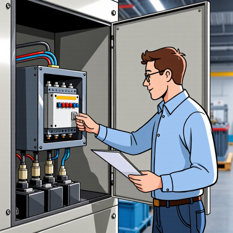
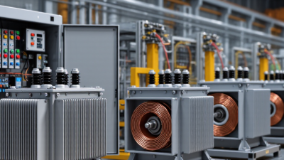
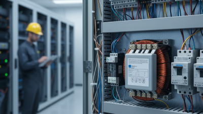
Choosing Control Transformers for global projects requires more than matching a voltage on a datasheet. Buyers must check the primary and secondary voltages, frequency, load, duty cycle, and installation environment. A transformer selected for a quiet, climate-controlled cabinet may behave differently in a hot, vibrating machine enclosure.
Start with the connected loads. Contactors, relays, and solenoids can draw brief inrush currents that exceed their steady-state demand. Compare the transformer’s inrush capacity and voltage regulation with the actual control circuit, not just its total wattage. Then verify insulation class, temperature rise, terminals, mounting dimensions, and protection requirements. Small details matter.
“Treat the nameplate as a starting point, then verify the real load and installation conditions,” says Alex Morgan, a fictional composite control-transformer specialist. This illustrative line is not a sourced quotation or a claim from a real expert. It expresses a practical selection principle: confirm every rating against the equipment, wiring diagram, and supplier documentation. Global buyers should also ask whether replacement units will be available and whether technical documents clearly state applicable ratings and test data. A purchase price can look attractive until a mismatched frequency, enclosure, or mounting pattern delays commissioning. That risk is easy to underestimate.
There is no universal best model. Share the complete load profile with the manufacturer, request written confirmation, and review the selection before ordering. I would still double-check the inrush assumptions; they are often less certain than the spreadsheet suggests.
A control transformer is a power transformer designed to supply control circuits in electrical equipment. It changes incoming voltage to a level suited to devices such as relays, contactor coils, sensors, and push buttons. Its purpose is not to run a whole production line. It provides dependable power for the commands that start, stop, and protect that equipment.
In a typical machine panel, the primary winding connects to the supply, while the secondary feeds the control circuit. When a contactor pulls in, its coil may briefly draw more current than it uses afterward. A correctly selected transformer can handle this inrush and help prevent control voltage from dipping. Small component, important job. You will find control transformers in machine tools, HVAC systems, packaging equipment, pump controls, and industrial panels. They are useful wherever control devices need a different voltage from the main supply.
For global buyers, check primary and secondary voltage, frequency, VA rating, and the expected load before comparing models. Also consider enclosure space, ambient temperature, and how the transformer will be mounted. A common oversight is sizing only for the steady load; coil inrush can change the requirement. That detail is easy to miss. Actual equipment data and qualified electrical review are more reliable than assumptions based on a similar machine.
Build a load schedule from equipment nameplates and control drawings. Add the volt-amperes of loads expected to operate together. For coils, include both sealed VA and pull-in VA; the latter can be much higher. Small loads mislead. For example, three contactors drawing 45 VA each during pull-in, plus 12 VA of lamps, create a 147 VA simultaneous demand. A 25% planning allowance gives about 184 VA, suggesting a 200 VA unit, subject to its inrush and voltage-drop ratings. Confirm the figures against the actual component data sheets; my example is only a screening calculation.
Match the primary winding or tap to the measured supply, not just the site’s nominal label. Then select a secondary voltage that matches every connected control device, such as 120 V for devices rated at 120 V. Check frequency, supply variation, secondary voltage drop, and simultaneous inrush. IEC 61558-2-2:2022 covers safety requirements for control transformers. The U.S. Department of Energy’s 2016 distribution-transformer technical support document uses 35% nameplate loading for dry-type efficiency comparisons; that is an efficiency test point, not a control-transformer sizing rule. Global installations vary, and a neat calculation can still miss a brief voltage sag. Verify the selection under the real operating sequence.
A control transformer should be selected by its real operating load, not just its panel dimensions. Compare primary and secondary voltage, frequency, and available tap settings against the supply at the installation site. Then calculate the combined VA demand of contactors, relays, and other connected devices. Check both steady-state load and the brief inrush current when coils energize; an undersized unit may cause control voltage to sag at startup. Allow sensible headroom, but avoid oversizing without reason. Copper and space still cost money.
Thermal and mechanical details matter, too. Review insulation class, temperature rise, ambient-temperature limits, altitude rating, mounting orientation, terminal access, and enclosure protection. Confirm whether the design and documentation meet the standards required for the destination market, such as applicable IEC or UL requirements. The IEA’s Electricity 2024 report projects global electricity demand will grow by an average 3.4% annually from 2024 to 2026, reinforcing the need to plan for dependable equipment in expanding electrical systems. That forecast is not a transformer-sizing rule. It is useful context, not a substitute for a load calculation. Before ordering, verify nameplate ratings and wiring diagrams against the actual panel design; a tidy spreadsheet can still miss a coil’s inrush.
For global buyers, safety approval is not a label to check at the end. IEC 61558-2-2:2022 addresses control-transformer safety, while UL 5085-2 covers safety requirements for certain low-voltage transformers. Confirm the required standard for the destination market, then check insulation, winding protection, terminal clearances, and enclosure rating. A cabinet mounted near washdown equipment needs different protection from a clean, dry control room. Small details count.
Operating conditions can change the right rating. IEC 60076-11:2018 gives reference service conditions for dry-type transformers: ambient temperature up to 40°C, a daily average of 30°C, an annual average of 20°C, and altitude up to 1,000 metres. These are useful screening values, not a substitute for the control transformer’s own datasheet. Above those conditions, ask about derating, cooling, and insulation limits. Also compare inrush current with the control devices it must energize; a contactor coil can demand several times its steady-state current at startup. That brief surge is easy to overlook. I would recheck it against the actual load list, especially when several coils switch together. A technically compliant unit can still run hot or cause nuisance trips if the enclosure is cramped or the supply voltage varies.
| Selection Dimension | What to Check | How It Affects Selection | Practical Buyer Action |
|---|---|---|---|
| Applicable safety standards | Determine the destination market and the standards applicable to the transformer and the finished equipment. IEC 61558-1 covers general requirements and tests for power transformers, power supplies, reactors, and similar products; IEC 61558-2-2 addresses particular requirements for control transformers. In North America, UL 5085-1 and UL 5085-2 cover general requirements and particular requirements for general-purpose and control transformers. | Required construction, testing, markings, and certification depend on the product type and market. A standard or approval used in one region does not automatically establish compliance in another. | Specify the destination countries, end-use equipment, and required approvals. Confirm the exact standard edition and certification scope with the supplier and the project’s compliance authority. |
| Input voltage and frequency | Record the nominal supply voltage, expected voltage variation, and supply frequency, such as 50 Hz, 60 Hz, or both. | The primary winding and magnetic design must suit the actual supply. A transformer rated for one frequency should not be assumed suitable at another unless its rating or manufacturer documentation confirms this. | Provide the supply-system details and check the nameplate ratings. For equipment intended for multiple regions, verify each intended voltage and frequency combination. |
| Secondary voltage and load | Identify the required control-circuit voltage and the connected devices, including contactor coils, relays, valves, and indicators. | The secondary voltage must match the control circuit. The connected load’s steady-state and starting requirements both affect transformer sizing. | List the loads and their voltage ratings. Check whether the control circuit requires one secondary voltage, multiple secondary connections, or a grounded reference. |
| Rated capacity and inrush | Compare the transformer’s rated volt-amperes (VA) with the combined load, including the starting or pickup VA of devices that can energize at the same time. | Coil inrush can be substantially higher than its sealed or holding demand. Undersizing may cause excessive voltage drop, contactor chatter, or failure of devices to pick up. | Use device manufacturer data for pickup and holding VA. Apply the transformer manufacturer’s sizing guidance and account for simultaneous operation rather than relying only on summed steady-state VA. |
| Ambient temperature and cooling | Check the expected air temperature around the transformer, ventilation, nearby heat sources, and the product’s stated temperature-rise or ambient ratings. | Higher ambient temperatures can reduce available thermal margin and shorten insulation-system life if the transformer operates beyond its ratings. | Compare the installation conditions with the nameplate and datasheet limits. Improve ventilation or select a suitable rating where the enclosure or surrounding equipment traps heat. |
| Altitude | Determine the installation altitude and compare it with the manufacturer’s stated rating conditions. | At higher altitude, reduced air density can affect cooling and dielectric performance. Any required rating adjustment is product- and standard-dependent. | Declare the actual altitude during specification and obtain manufacturer confirmation if it exceeds the stated conditions for the product. |
| Duty cycle and switching frequency | Assess whether loads operate continuously, intermittently, or in frequent switching cycles, and identify simultaneous load conditions. | Repeated energization and sustained loading influence thermal performance and the required capacity. Control circuits with frequent operation may have different demands from lightly loaded circuits. | Describe the operating sequence and worst-case load combination. Check the manufacturer’s continuous-duty and application guidance. |
| Insulation and electrical separation | Review the required isolation, insulation level, dielectric test information, and separation between primary and secondary circuits for the equipment design. | Electrical separation and insulation coordination are essential to protection against electric shock and electrical faults. Requirements depend on the equipment standard and system design. | Confirm the required insulation and isolation characteristics with the equipment designer. Do not treat a control transformer as a substitute for protective grounding or other required safeguards. |
| Protection and fault coordination | Check primary and secondary overcurrent protection requirements, available fault current, conductor sizing, and applicable equipment rules. | Correctly selected protection helps limit damage from overloads and short circuits. Device selection and placement depend on the transformer design and the governing electrical code or product standard. | Follow the transformer documentation and applicable local rules. Coordinate protective devices with the transformer’s ratings and the control-circuit conductors. |
| Enclosure and environmental exposure | Consider indoor or outdoor location, dust, moisture, corrosion, vibration, and the enclosure’s required ingress-protection or enclosure rating. | The installed protection level is determined by the complete assembly and environment; an open-type transformer alone may not provide protection against dust or water. | Specify the installation environment and required enclosure rating for the assembled equipment. Check that ventilation needs are compatible with the enclosure design. |
| Mounting, wiring, and serviceability | Check available panel space, mounting orientation, terminal access, conductor range, clearances, and expected maintenance access. | Physical fit and accessible terminals affect safe installation, heat dissipation, and ease of replacement. | Review outline drawings and terminal details before purchase. Verify mounting instructions and required electrical clearances for the application. |
| Documentation and market access | Request the nameplate data, wiring diagram, installation instructions, test information, and evidence of the approvals required for the destination market. | Complete documentation supports equipment integration, inspection, traceability, and verification that the selected product matches the specified application. | Make approval and documentation requirements part of the purchase specification, and confirm that the supplied model and configuration are covered. |
Choosing control transformers across borders takes more than comparing voltage, VA rating, and price. Ask suppliers for test reports tied to the exact model, winding configuration, and insulation system. Check whether certification covers the destination market and intended installation; a certificate for a product family may not cover every variant. Standards such as IEC 61558-2-2 can help frame safety checks, but confirm requirements with the buyer and local approval body. Paperwork is not proof.
Assess practical supplier controls, too. Request a sample, routine-test records, material traceability, and a clear process for handling defects. Test the transformer at the specified input voltage and frequency, then check output under load and temperature rise. Ask how lead times change when copper, laminations, or other components are delayed. One detail is easy to miss: who pays for re-testing after a design change?
Logistics deserve equal scrutiny. UNCTAD’s Review of Maritime Transport 2024 reports that more than 80% of world trade by volume moves by sea, so packaging and shipment planning matter. Ask for moisture barriers, firm internal bracing, export packing dimensions, and spare-unit options. The World Bank’s 2023 Logistics Performance Index compares 139 economies across customs, infrastructure, shipment arrangements, and delivery reliability. Use it as context, not a supplier scorecard. A capable supplier should explain the route, handoff points, and contingency plan in plain terms. I would still challenge optimistic delivery promises; port delays rarely respect a spreadsheet.