Leave Your Message
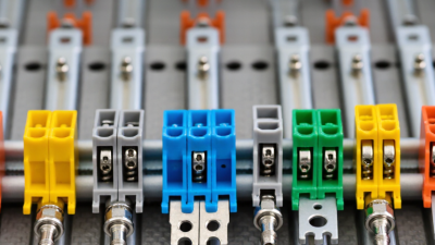
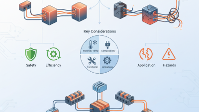
Choosing the right Wire Terminal Block in 2026 requires more than comparing prices or counting connection points. A reliable selection begins with the actual installation environment. Consider conductor size, rated current, voltage, temperature, vibration, moisture, and available cabinet space. A terminal block that works well on a quiet control panel may fail in a machine exposed to constant movement. Small details matter.
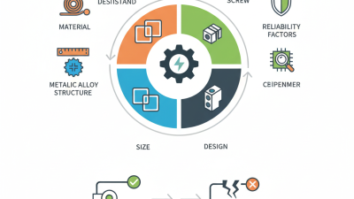
Start with the wire itself. Check whether the design uses solid, stranded, or fine-stranded conductors. Confirm the required clamping method, stripping length, and compatible accessories. Spring-clamp terminals can save maintenance time, while screw terminals may suit applications requiring familiar inspection and retightening procedures. Always verify manufacturer data, testing information, and applicable industry requirements before approval. Do not rely on appearance alone.
Field experience also reveals a common mistake: choosing a higher current rating without checking heat buildup. Crowded rows, oversized conductors, and poor ventilation can change real operating conditions. Leave practical space for ferrules, jumpers, labels, and test probes. It helps to examine the block beside the actual enclosure, not only on a computer screen. That step is easy to skip.
No selection is perfect. The best choice balances safety, serviceability, cost, and future expansion. Compare documented specifications from established manufacturers, question unclear ratings, and record why each feature matters. A careful decision today can reduce loose connections, troubleshooting delays, and replacement work later. Still, review the design again before production; assumptions often hide in the smallest terminal.
How to Choose a Wire Terminal Block in 2026?
Define the electrical requirements before comparing terminal block designs. Record the system voltage, continuous current, short-term overload, and AC or DC conditions. Do not rely on the nominal current alone. Heat rises when several circuits share a narrow enclosure. Check the wire size, conductor material, insulation diameter, and stripping length. A terminal block rated for 20 amperes may perform differently with small, tightly packed conductors.
Temperature matters.
Review the operating range, surrounding heat, and expected duty cycle. Confirm creepage and clearance distances for the working voltage. In damp or dusty locations, examine the enclosure rating and corrosion resistance. Use verified technical data, test reports, and installation instructions rather than sales descriptions. A qualified electrician or engineer should confirm requirements for critical equipment.
Mechanical requirements deserve equal attention. Measure available rail space, terminal pitch, wire-entry direction, and tool access. Check whether the connection must tolerate vibration, repeated servicing, or accidental cable pulling. Tightening torque is important; too little can create resistance, while too much may damage the clamp. During field commissioning, I have seen an electrically suitable block fail because the wire bend radius was ignored. That mistake is easy to make. Leave room for labeling, inspection, and future maintenance. Recheck the design with the actual wire and screwdriver, not only a drawing. Sometimes the neatest layout is not the most serviceable one.
| Requirement Category | Selection Parameter | Typical Design Range or Criterion | Why It Matters | Recommended Verification Method |
|---|---|---|---|---|
| Electrical | Rated working voltage | Choose a rating equal to or higher than the system voltage, including the applicable overvoltage category and pollution degree. | Voltage rating depends on insulation spacing, creepage distance, clearance, housing material, and the applicable safety standard. | Compare the application voltage with the terminal block certification and spacing data in the technical datasheet. |
| Electrical | Rated current | Select a current rating above the continuous operating current; allow additional margin for ambient temperature and grouping. | Heating at the conductor, contact, and clamping point can reduce reliability and may require derating. | Check the test current, conductor size, ambient temperature, and derating curve rather than relying only on a headline rating. |
| Electrical | Conductor cross-section | Common ranges include approximately 0.2–2.5 mm², 0.5–6 mm², and larger sizes for power distribution. | The conductor range must match the wire size, insulation diameter, ferrule size, and permitted clamping geometry. | Confirm both solid and stranded wire ranges, including AWG equivalents where applicable. |
| Electrical | Wire type compatibility | Verify compatibility with solid, stranded, fine-stranded, flexible, or ferruled conductors as required. | Different conductor constructions require different clamp designs and preparation methods. | Review the approved conductor types and perform a pull-out and resistance check using the intended wire preparation. |
| Electrical | Contact resistance | Prefer a stable, low-resistance connection that remains within the applicable standard limits after environmental and mechanical testing. | Low and stable contact resistance minimizes voltage drop, heat generation, and long-term degradation. | Measure initial resistance and resistance after temperature cycling, vibration, and current-loading tests. |
| Electrical | Insulation performance | Check insulation resistance, dielectric withstand voltage, creepage distance, and clearance for the intended environment. | Insulation performance prevents leakage, flashover, and unintended conduction between adjacent circuits. | Use the relevant product and installation standard for minimum spacing and dielectric test requirements. |
| Thermal | Operating temperature | Select a suitable range for the installation, commonly including at least −40 °C to +85 °C or higher for demanding applications. | Temperature affects current capacity, plastic strength, contact force, insulation life, and thermal expansion. | Assess the highest local temperature, self-heating, enclosure conditions, and required derating. |
| Environmental | Humidity, condensation, and corrosion | For humid, dusty, salty, or corrosive locations, use suitable materials, sealing, surface finishes, and enclosure protection. | Moisture and contaminants can lower insulation resistance and accelerate corrosion at the contact interface. | Evaluate the enclosure IP rating, chemical exposure, condensation risk, and required environmental test level. |
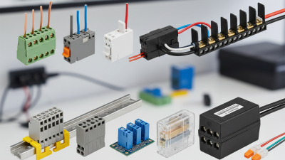
| Mechanical | Mounting method | Choose the required mounting format, such as DIN-rail, panel, PCB, feed-through, or direct chassis mounting. | The mounting method determines installation time, mechanical retention, serviceability, and available panel space. | Confirm rail profile, hole pattern, PCB pitch, locking features, and clearance around the installed terminal. |
| Mechanical | Terminal pitch and density | Common pitches include approximately 2.54 mm, 3.5 mm, 5.0 mm, 5.08 mm, 7.5 mm, and 10.16 mm. | Pitch affects insulation spacing, allowable wire size, screwdriver access, panel width, and heat dissipation. | Check the required voltage spacing, adjacent terminal clearance, tool access, and wiring bend radius. |
| Mechanical | Connection technology | Select screw clamp, spring clamp, push-in, insulation-displacement, or crimp-based technology according to the application. | Connection technology affects vibration resistance, installation speed, maintenance, tool requirements, and conductor preparation. | Compare the specified wire range, insertion force, release method, torque requirement, and retightening requirements. |
| Mechanical | Tightening torque | Use only the manufacturer-specified torque for the selected terminal and conductor size; do not estimate torque from screw size alone. | Insufficient torque can cause loosening and overheating, while excessive torque can damage threads, clamps, or conductors. | Use a calibrated torque tool and verify torque retention after vibration or thermal cycling where required. |
| Mechanical | Wire retention and pull-out strength | The terminal should retain the prepared conductor without damage when tested according to the applicable standard. | Adequate retention prevents intermittent faults caused by vibration, cable movement, or installation stress. | Perform a pull test using the specified conductor type, ferrule, insertion depth, and tightening or actuation procedure. |
| Mechanical | Vibration and shock resistance | For transport, machinery, automotive, or mobile equipment, select a connection system tested for the expected vibration and shock profile. | Mechanical movement can reduce contact force, loosen screws, and create intermittent electrical connections. | Review vibration and shock test results and test the complete assembly, including wires, ferrules, rail, and enclosure. |
| Materials | Insulating housing material | Prefer flame-retardant insulating materials with suitable temperature index, tracking resistance, and chemical compatibility. | The housing must maintain insulation and mechanical integrity throughout the product's expected service life. | Check flammability classification, comparative tracking performance, continuous-use temperature, and chemical resistance data. |
| Materials | Conductor and contact materials | Common choices include copper alloys with protective surface finishes selected for conductivity and corrosion resistance. | Material and plating influence contact stability, resistance to oxidation, current capacity, and compatibility with the conductor. | Review the contact material, plating, compatibility with copper or aluminum conductors, and environmental limitations. |
| Installation | Accessibility and serviceability | Provide sufficient space for stripping, ferrule insertion, screwdriver access, test points, labeling, and wire bending. | Good access reduces wiring errors, installation damage, inspection time, and maintenance risk. | Create a full-scale panel or CAD layout that includes tools, wire ducts, bend radius, labels, and neighboring components. |
| Compliance | Applicable standards and approvals | Identify the standards required for the equipment, such as industrial control, machinery, building wiring, railway, marine, or hazardous locations. | The required approval depends on the end product, installation location, voltage system, and target market. | Confirm current certificates, test reports, marking requirements, and approval conditions for the complete terminal assembly. |
| Lifecycle | Availability and replacement strategy | Define required service life, interchangeability, documentation, traceability, and long-term availability before design release. | A technically suitable terminal can still create risk if replacement parts, tooling, or approved alternatives are unavailable. | Document the exact electrical and mechanical envelope, approved substitutes, tooling, and inspection criteria. |
Note: Final ratings and dimensions must be confirmed against the current technical documentation and the applicable installation or product standard. Electrical ratings may require derating based on conductor size, ambient temperature, terminal grouping, and enclosure conditions.