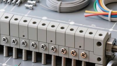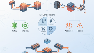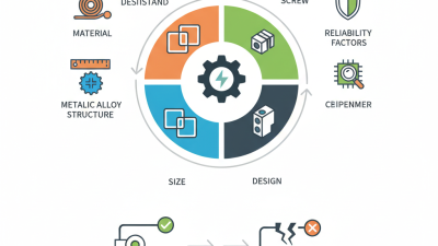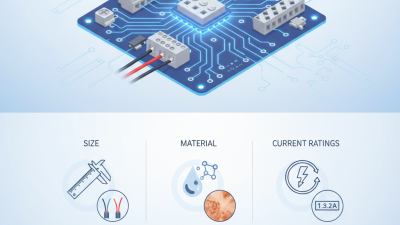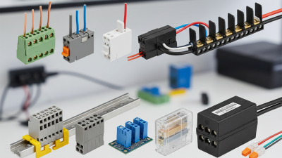
Choosing the right Wire Terminal Block is a small decision with large consequences. A loose conductor can create heat, intermittent signals, or costly downtime. Inside a control cabinet, those risks may begin with one poorly matched clamp.
Industry data shows why selection deserves more attention. MarketsandMarkets valued the global terminal block market at approximately USD 3.9 billion in 2023. Its report projects continued growth through 2028, driven by industrial automation, renewable energy, and transportation systems. Fortune Business Insights also identifies electrification and advanced control equipment as major demand factors. These figures are useful, but imperfect. Market estimates vary by product definition, region, and reporting method.
The practical question is not simply, “Which block fits?” It is, “Which connection will remain safe and stable under real conditions?” Consider conductor size, current rating, voltage, temperature, vibration, ingress protection, and installation space. Check whether the block accepts solid, stranded, or ferruled conductors. Then verify torque values and approval markings against the applicable project requirements.
Electrical engineer and educator Mike Holt often stresses the importance of reliable terminations: “The connection is only as good as the termination.” That reminder sounds obvious. It is still frequently overlooked. A terminal block may look robust on a workbench, yet fail after repeated thermal cycling or vibration.
This guide examines the details that matter, from screw and spring-clamp designs to material quality and certification evidence. It also questions a common shortcut: choosing the cheapest compatible part. Compatibility is not durability. A careful choice protects equipment, maintenance teams, and the people who depend on the installation.
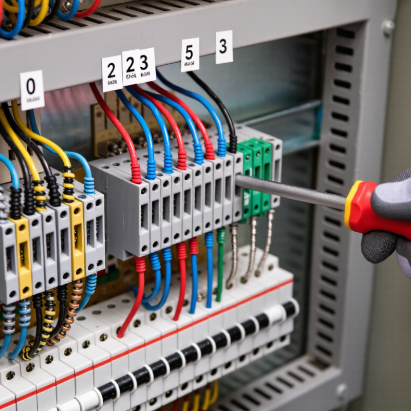
Choosing the right wire terminal block begins with the application, not its appearance. Define the circuit voltage, operating current, wire size, and conductor type. Check whether the circuit uses solid, stranded, or finely stranded wire. Each type may require a different clamping method or ferrule.
Keep the installation purpose clear. Is it for power distribution, signal wiring, control equipment, or frequent maintenance? A compact block may suit a control cabinet, while higher current requires larger contacts and stronger insulation. Confirm the rated voltage and current under the expected temperature. Ratings can decrease as heat builds.
The wiring environment matters just as much. Record the surrounding temperature, humidity, vibration, dust, and chemical exposure. Outdoor cabinets may face condensation after a cold night. Machinery can loosen poorly secured connections through repeated movement. In dusty areas, select suitable protection and maintain enough spacing for inspection.
I once saw a connection fail because the wire size matched, but the terminal screw was under-tightened. Small details matter. Follow the specified torque and use a calibrated tool when possible. Check insulation clearance, mounting strength, labeling space, and access for testing. Review the applicable electrical standards and installation instructions before approval.
Do not rely only on a catalog rating. Test a sample with the actual wire, enclosure, and load. Measure temperature rise after continuous operation. A design that looks correct on paper may still be difficult to maintain. That weakness deserves attention before production.
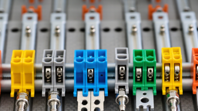
Choosing a wire terminal block starts with the conductor, not the cabinet shape. Solid, stranded, and fine-stranded wires need different clamping designs. Screw, spring-clamp, and push-in types each handle vibration and maintenance differently. A spring clamp can resist loosening, but it may require a specific stripping length. Check the manufacturer’s technical sheet carefully.
IEC 60947-7-1 defines requirements for terminal blocks used with copper conductors, including electrical ratings and temperature performance. UL 1059 also evaluates terminal blocks for safety and construction. These standards matter when voltage, current, and fault conditions increase. MarketsandMarkets’ 2024 Terminal Blocks Market report forecasts a compound annual growth rate of about 5.4% through 2029. That growth reflects expanding control panels, factory automation, and power distribution equipment.
Mounting method deserves equal attention. DIN-rail blocks suit modular panels and simplify replacement. Panel-mount blocks work better where direct enclosure fixing improves mechanical support. Barrier strips can provide clear separation, but they consume more panel space. Leave room for wire bending and a test probe. A neat layout can still be wrong. In panel reviews, a recurring mistake is selecting a block by current rating alone. Heat, conductor size, tightening torque, spacing, and ingress protection can change the result. I would verify these details against IEC or UL documentation before approving the design.
Choosing a wire terminal block starts with electrical ratings, not appearance. Check rated voltage, continuous current, and short-circuit withstand capacity. A terminal marked 600 V may still require derating under heat or grouping conditions. Ambient temperature matters.
NFPA’s Fire Loss in the United States, 2023, reported about 374,300 residential structure fires. Electrical distribution and lighting equipment appeared in roughly 25,700 of those fires. These figures show why secure connections deserve careful attention. Select terminals tested under applicable requirements, such as IEC 60947-7-1 or UL 1059. Confirm creepage, clearance, flame resistance, and finger protection. Safety markings are not decoration.
Wire compatibility is equally important. IEC 60228 classifies conductors by construction and flexibility. A terminal designed for solid wire may not grip finely stranded wire correctly. Match conductor size, material, insulation diameter, and stripping length. Then verify the manufacturer’s torque range, even without naming the manufacturer. Too little torque creates resistance and heat. Too much torque can damage the conductor.
A practical check helps. Pull the wire gently. Inspect exposed copper. None should extend beyond the clamp. I would not rely on color alone. Vibration, oxidation, and repeated thermal cycling can change a connection over time. No checklist is perfect. Recheck tightness during scheduled maintenance, especially in crowded panels or high-load circuits.
Choosing a wire terminal block starts with its environment, not its appearance. Polyamide bodies suit many control panels because they balance insulation, strength, and cost. In damp or chemically exposed areas, inspect the material’s temperature, flammability, and resistance ratings. Copper-alloy clamps usually provide stable conductivity, while plated surfaces can reduce oxidation. Do not assume a shiny terminal is a better terminal.
Connection design changes installation quality. Screw clamps are familiar and useful for maintenance, but tightening torque must match the specification. Spring-clamp designs can maintain contact under vibration and thermal cycling. Push-in terminals reduce tool time, especially in repetitive wiring. A 2023 report from the International Federation of Robotics recorded 541,302 industrial robots installed worldwide in 2022, showing why faster panel assembly matters in automated facilities. Still, speed can hide errors. A hurried insertion is not a reliable connection.
Installation features deserve equal attention. Look for clear circuit markings, test points, end stops, and DIN-rail compatibility. IEC 60947-7-1 provides requirements for terminal blocks used in low-voltage switchgear assemblies. UL 1059 also evaluates terminal-block performance, including electrical and mechanical considerations. Independent market research from MarketsandMarkets forecasts continued growth in the global terminal block market through 2028, driven partly by industrial automation and control-panel demand. Forecasts vary by research method. That uncertainty matters. Select the wire range, insulation rating, short-circuit suitability, and spacing from the actual application—not from a catalogue photograph.
| Terminal Block Type | Typical Insulating Material | Typical Conductor Material | Connection Design | Typical Wire Range | Electrical and Environmental Characteristics | Installation Features | Best Suited For |
|---|---|---|---|---|---|---|---|
| Screw-Clamp Terminal Block | Polyamide, polycarbonate, or thermoplastic polyester housing | Nickel-plated or tin-plated copper alloy clamp and current bar | Wire is secured by tightening a screw against a clamp or pressure plate | Commonly approximately 0.2–35 mm², depending on the design | Reliable and widely available; performance depends on correct tightening torque and periodic inspection in high-vibration applications | Simple hand-tool installation; ferrules are recommended for finely stranded conductors; torque-controlled screwdrivers improve consistency | General control panels, distribution equipment, and maintenance-friendly installations |
| Spring-Clamp Terminal Block | Polyamide, polycarbonate, or other flame-retardant engineering thermoplastics | Usually tin-plated copper alloy | Spring force maintains contact pressure on the conductor | Commonly approximately 0.2–16 mm², depending on the terminal design | Resists loosening caused by vibration and thermal cycling; generally provides consistent contact pressure over time | Push-button, screwdriver-release, or lever-operated insertion; faster wiring than screw-clamp designs in many applications | Vibration-prone machinery, compact control cabinets, and high-volume wiring |
| Push-In Terminal Block | Flame-retardant polyamide or polycarbonate | Tin-plated copper alloy current path with spring contact | Rigid conductors or ferruled stranded conductors are pushed directly into the contact chamber | Commonly approximately 0.2–6 mm², depending on the product family | Fast connection with stable spring pressure; conductor preparation requirements vary by design | Minimal tool use; release slot or push button is normally provided for removal; ferrules may be required for stranded wire | High-density panels, machine building, and applications requiring rapid assembly |
| Barrier Terminal Block | Thermoplastic, thermoset resin, or ceramic in high-temperature versions | Nickel-plated or tin-plated brass or copper alloy | Screw terminals are separated by raised insulating barriers | Commonly approximately 0.5–16 mm², with larger sizes available | Good conductor separation and straightforward inspection; barrier height can help reduce accidental contact between adjacent circuits | Often panel-mounted with screws; ring or fork terminals are frequently used; clearances must be checked for the application voltage | Power distribution, equipment wiring, and circuits requiring visible conductor separation |
| DIN-Rail Feed-Through Terminal Block | Flame-retardant polyamide or polycarbonate | Tin-plated copper alloy | One or more connection technologies arranged in a modular body | Commonly approximately 0.2–240 mm², depending on the frame size | Efficient use of panel space; voltage and current ratings depend on conductor size, spacing, and terminal construction | Snaps onto standardized DIN rails; end stops, separators, markers, and jumper bars can create an organized wiring system | Industrial control cabinets, automation panels, and modular distribution assemblies |
| PCB Terminal Block | Polyamide, polycarbonate, or high-temperature thermoplastic | Tin-plated copper alloy pins and clamp components | Screw, spring-clamp, or pluggable connection mounted directly to a printed circuit board | Commonly approximately 0.2–10 mm², depending on pitch and housing size | Provides a detachable or fixed wire interface for electronic assemblies; PCB layout and creepage distances are critical | Through-hole or surface-mount versions are available; pluggable types simplify equipment servicing and field replacement | Power supplies, industrial electronics, instrumentation, and control boards |
| Pluggable Terminal Block | Flame-retardant polyamide or polycarbonate | Tin-plated copper alloy plug and header contacts | Wire connection is made in a removable plug that mates with a fixed header | Commonly approximately 0.2–10 mm², depending on the connector series | Enables quick disconnection while preserving wire order; contact rating depends on pitch, conductor size, and mating design | Supports pre-wiring, tool-free module replacement in some designs, and coding or locking accessories for error prevention | Replaceable control modules, field service equipment, and multi-section assemblies |
| High-Temperature Ceramic Terminal Block | Alumina or steatite ceramic body | Nickel-plated brass, copper alloy, or heat-resistant metal parts | Usually screw-clamp connection with a heat-resistant insulating body | Commonly approximately 0.5–10 mm², depending on the construction | Suitable for temperatures beyond the capability of many thermoplastic housings; thermal limits of screws, conductors, and surrounding equipment still apply | Typically panel- or surface-mounted; installation should allow for heat dissipation and appropriate conductor insulation ratings | Heating equipment, ovens, lighting fixtures, and other elevated-temperature applications |
| Grounding Terminal Block | Polyamide or polycarbonate housing, often colored green and yellow | Metal grounding foot or clamp, commonly zinc-plated or tin-plated steel/copper alloy | Conductor is connected to a metal element bonded directly to the DIN rail or grounding system | Commonly approximately 0.2–35 mm², depending on the model | Designed to provide protective bonding; the grounding path must meet the applicable installation standard and fault-current requirements | Snaps onto a compatible DIN rail and may eliminate a separate grounding wire to the rail when the rail is correctly bonded | Protective earth connections in industrial control cabinets and distribution panels |
Choosing a wire terminal block requires more than checking current and voltage ratings. Verify conformity with IEC 60947-7-1, conductor compatibility, temperature limits, and short-circuit performance. The housing should resist cracking, discoloration, and deformation near heat sources. Check the datasheet, not just the package.
Maintenance needs deserve equal attention. A practical inspection includes torque verification, conductor insertion depth, looseness, corrosion, and visible heat marks. One uncomfortable truth: a clean plastic body proves little. Loose connections may heat internally before damage becomes visible. NFPA’s Home Structure Fires report for 2016–2020 found electrical distribution and lighting equipment involved in 24% of reported home fires. That figure supports routine inspection, especially in vibrating panels or high-load circuits. It does not prove that every terminal failure causes a fire.
Long-term reliability depends on installation quality and repeatable maintenance. The U.S. Department of Energy’s Operations and Maintenance Best Practices Guide cites typical predictive-maintenance savings of 8–12% over preventive maintenance, and up to 40% over reactive maintenance. For terminal blocks, this means recording torque values, inspection dates, load conditions, and replacement reasons. Use calibrated tools and follow the manufacturer’s specified torque range. Over-tightening can damage the terminal. Under-tightening can create resistance. I would also review failures honestly; sometimes the chosen block was acceptable, but the enclosure, conductor size, or maintenance plan was not.
Verify quality, maintenance needs, and long-term reliability before installation.
The chart shows typical preventive inspection planning intervals for terminal blocks in different operating environments. Cleaner environments generally require less frequent inspection, while vibration, dust, humidity, and corrosive exposure require shorter intervals. Always confirm the final interval with the applicable electrical standard, installation conditions, and product instructions.