Leave Your Message
Choosing the right Current Transformer is more than matching a ratio to a datasheet. It is a protection and measurement decision that affects safety, accuracy, and maintenance. A small mismatch can distort readings or delay protective action.
Begin with the primary current, expected overload, and system voltage. Then examine the secondary rating, burden, accuracy class, and operating frequency. A 400/5 A transformer may appear suitable, yet connected meters and long cables can exceed its burden limit. That detail is easy to overlook. The core may saturate during a fault, producing misleading protection signals. For revenue metering, measurement accuracy matters greatly. For relay protection, fault performance and saturation behavior usually deserve greater attention.
Physical installation also influences selection. Check the window size, conductor arrangement, insulation level, and available cabinet space. Split-core designs can simplify retrofits, but they may not match the stability of fixed-core models. Always verify manufacturer data, relevant standards, and the complete circuit design. An experienced engineer should review the application rather than trust one catalogue value.
Real projects rarely behave perfectly. Load profiles change, cables are rerouted, and future expansion is often underestimated. That is why selection should include reasonable operating margins and documented assumptions. Ask what happens during startup, overload, and short-circuit conditions. A reliable Current Transformer is not merely accurate on paper. It must remain dependable in the actual panel, under the actual electrical conditions, for years. Recheck the choice before installation. Small doubts are worth investigating.
How to Choose the Right Current Transformer?
Understanding Current Transformer Types and Their Applications
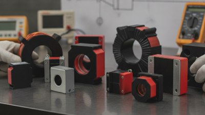
Current transformers differ by construction, accuracy, and purpose. Wound CTs suit lower primary currents and dedicated measurement circuits. Bar-type CTs handle larger conductors in switchgear. Window and toroidal CTs surround existing conductors, making them useful for compact panels. Split-core models simplify retrofit work, but their hinged joints can reduce accuracy if installation is careless. Small gaps matter.
Metering CTs prioritize accuracy during normal loads. Protection CTs must remain stable during faults and resist saturation. For earth-fault detection, core-balance CTs measure the residual current around all live conductors. The correct choice depends on ratio, burden, insulation level, frequency, and accuracy class. A 400/5 A ratio may be unsuitable if the actual load stays near 20 A. The signal could become too weak for dependable monitoring.
Field experience shows that cable placement often affects results more than expected. Keep the conductor centered, tighten terminals, and verify polarity before energizing. Never leave an energized CT secondary open; dangerous voltage can develop. The International Energy Agency reported in Electricity Grids and Secure Energy Transitions that annual grid investment must exceed 600 billion dollars by 2030, nearly double current levels. This expansion increases demand for reliable measurement and protection. IEC 61869-2 provides key requirements for inductive CTs, but site conditions still require engineering judgment. Specifications alone are not enough.
| Current Transformer Type | Construction and Operating Principle | Typical Current Range | Accuracy and Output | Common Applications | Key Advantages | Important Selection Considerations |
|---|---|---|---|---|---|---|
| Type 1 Solid-Core Current Transformer |
A fixed magnetic core surrounds a primary conductor or includes a primary winding. The secondary winding produces a proportional current for measurement or protection. | From low-current measurement circuits to high-current distribution and power-system applications; the exact range depends on the design and ratio. | Commonly available in metering classes such as 0.1, 0.2, 0.5, or 1.0, and protection classes such as 5P or 10P. Secondary output is often 1 A or 5 A. | Switchboards, motor control centers, power meters, protective relays, generators, transformers, and utility substations. | High accuracy, strong mechanical stability, and suitability for continuous service in permanent installations. | Installation usually requires disconnecting or isolating the primary conductor. Verify window or mounting dimensions, insulation level, burden, ratio, and short-circuit withstand rating. |
| Type 2 Split-Core Current Transformer |
The magnetic core opens on a hinge or removable joint so it can be installed around an existing cable without disconnecting the conductor. | Typically used for low- to medium-current monitoring, with available ratios selected according to the conductor current and measurement system. | Usually designed for monitoring and metering rather than the highest-accuracy protection duties. Output may be 1 A, 5 A, or a low-level voltage signal through an integrated circuit. | Energy monitoring, retrofit projects, building automation, HVAC systems, data centers, and facility-level power management. | Fast installation, minimal downtime, and convenient use in existing electrical panels. | Check core-joint alignment, conductor position, closing force, accuracy at the actual load current, and whether the device is suitable for the available space and cable size. |
| Type 3 Rogowski Coil |
An air-core flexible coil senses the rate of change of current. An electronic integrator converts the signal into a current-proportional output. | Well suited to large conductors and broad current ranges, including high-current and transient measurements. | Provides a low-level voltage output, commonly specified in mV per kA or similar units. It does not saturate like a conventional iron-core CT, but it requires suitable signal conditioning. | Portable analyzers, power-quality monitoring, temporary measurements, large busbars, variable-frequency drives, and retrofit installations. | Flexible, lightweight, easy to install around large conductors, and capable of measuring rapidly changing currents. | Requires an integrator or compatible meter. Check frequency range, phase error, coil length, positioning, electromagnetic interference, and the required power supply for the electronics. |
| Type 4 Window-Type Current Transformer |
A toroidal core has a central opening through which the primary conductor passes. The conductor itself acts as the primary winding, often with one primary turn. | Used across low-, medium-, and high-current systems, depending on the core size, insulation design, and secondary ratio. | Available in measurement and protection classes. Multiple primary passes through the window can increase the effective primary turns and change the current ratio. | Busbars, cables, switchgear, panelboards, feeder monitoring, earth-fault protection, and industrial distribution systems. | Simple primary arrangement, good insulation separation, and flexible ratio options without a dedicated primary winding. | Confirm that the conductor or busbar fits through the aperture. Keep the conductor centered when required, and account for the number of primary passes when calculating the ratio. |
| Type 5 Bar-Type Current Transformer |
The primary is an integral insulated or uninsulated bar passing through the magnetic core. The bar is connected directly into the power circuit. | Commonly selected for medium- and high-current switchgear and distribution equipment. | Can provide accurate metering or protection performance. The primary bar and insulation system are rated for a defined continuous current and short-circuit duty. | Switchboards, metal-enclosed switchgear, busbar systems, industrial feeders, and medium-voltage equipment. | Robust construction, consistent primary geometry, and high suitability for factory-built electrical assemblies. | Check terminal configuration, phase spacing, creepage and clearance, insulation level, thermal rating, short-time current rating, and mounting orientation. |
| Type 6 Bushing Current Transformer |
The CT is installed around an insulated bushing that carries the high-voltage conductor. The bushing conductor provides the primary path through the core. | Generally used in medium- and high-voltage apparatus, including transformers and gas- or air-insulated switchgear. | Designed for metering, protection, or both. Accuracy and insulation performance are coordinated with the host equipment and system voltage. | Power transformers, circuit breakers, generator transformers, high-voltage switchgear, and substation equipment. | Compact integration, reduced external wiring, and effective use of existing high-voltage insulation structures. | Verify compatibility with the bushing diameter, insulation coordination, creepage distance, thermal limits, ratio, burden, and protection requirements. |
| Type 7 Protection Current Transformer |
A CT designed to reproduce fault currents sufficiently for protective relays while delaying magnetic saturation under specified fault conditions. | Selected according to the normal primary current, fault level, relay requirements, and system protection scheme. | Typical IEC protection designations include 5P and 10P. Special protection classes may be required for differential, high-impedance, or transient-performance applications. | Overcurrent, earth-fault, differential, restricted earth-fault, distance, and busbar protection systems. | Supports dependable relay operation during short-circuit conditions when correctly matched to the protection circuit. | Evaluate accuracy-limit factor, knee-point voltage, secondary resistance, total burden, remanence, fault current, and the relay manufacturer's input requirements. |
| Type 8 Metering Current Transformer |
A CT optimized for accurate current reproduction during normal operating conditions and specified measurement ranges. | Selected around the normal operating current so the meter operates near its best accuracy range without excessive underloading. | Common accuracy classes include 0.1, 0.2, 0.5, and 1.0, depending on the measurement purpose and applicable standard. | Revenue metering, energy management, power meters, load monitoring, and electrical instrumentation. | Good measurement accuracy and predictable performance at normal load levels. | Match the ratio to the expected load, verify accuracy over the required current range, calculate connected burden, and confirm the applicable standard and test requirements. |
| Type 9 Zero-Sequence or Core-Balance CT |
All phase conductors, and the neutral where applicable, pass through one core. Residual flux indicates current flowing to earth or through an unintended return path. | Usually selected for residual-current or earth-fault detection rather than for measuring the full phase current. | Output and sensitivity depend on the protection relay or residual-current monitor. The core must accommodate all conductors that form the intended current path. | Earth-leakage protection, ground-fault relays, cable feeders, motor circuits, and low-voltage distribution systems. | Can detect small residual currents without separately measuring each phase conductor. | All relevant conductors must pass through the core in the correct arrangement. Check aperture size, pickup level, conductor symmetry, shielding, and relay compatibility. |
Selection reminder: Before choosing a current transformer, confirm the primary current and fault current, system voltage, frequency, required accuracy class, secondary current or voltage, connected burden, insulation level, installation method, environmental conditions, and the applicable electrical standard. Never leave a conventional CT secondary open while current is flowing in the primary; use the specified shorting or protection procedure.