Leave Your Message

How to Choose a Current Transformer in 2026?

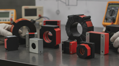
Choosing a Current Transformer in 2026 requires more than comparing ratios, prices, or delivery dates. It demands a clear understanding of the electrical system, protection requirements, installation environment, and future measurement needs. A device installed beside a 400 kVA transformer faces different demands from one serving a high-voltage substation. Accuracy, burden, insulation level, short-circuit performance, and saturation behavior all matter.

Protection engineer Steven E. Zocholl puts the principle plainly: “A current transformer must reproduce primary current accurately when the system needs it most.” That sentence deserves attention. During a fault, a poorly selected Current Transformer can saturate, distort relay input, and delay a correct trip. The result may be overheating, nuisance operation, or expensive equipment damage. Small details matter. Check the secondary rating, such as 1 A or 5 A. Confirm the required accuracy class. Review the actual cable length and relay burden, not only the catalog specification.

Real projects are rarely perfect. Available space may be limited. Existing wiring may create unexpected burden. Some specifications may also be copied from older systems without review. That is where careful engineering becomes valuable. This guide explains how to compare core types, ratios, classes, materials, and testing requirements in 2026. It also considers digital protection, energy monitoring, connected substations, and supply reliability. The best choice is not always the most advanced model. It is the Current Transformer that remains accurate, stable, testable, and suitable for the system’s real operating conditions.

How to Choose a Current Transformer in 2026?

Define the Application and Current Measurement Requirements

How to Choose a Current Transformer in 2026?

Choosing a current transformer in 2026 starts with the application, not the catalog. Define whether it serves metering, protection, control, or a combination. A factory feeder carrying 800 A needs different behavior from a 100 A laboratory panel. Record nominal current, maximum load, overload duration, system voltage, frequency, and fault level. Do not estimate from the nameplate alone. Real loads change.

Select a primary rating close to the measured current while allowing credible overloads. An oversized transformer may reduce low-current accuracy, especially when energy meters monitor light loads. Specify the secondary output, commonly 1 A or 5 A, and verify instrument compatibility. Calculate total burden from lead resistance, terminals, meters, and protective devices. Long copper runs can quietly consume the accuracy margin. This detail is often missed. For protection, check the accuracy limit factor, saturation behavior, and required class with a qualified engineer.

Installation conditions matter as much as electrical ratings. Measure conductor size, window clearance, temperature, vibration, and mounting space. Split-core units can simplify retrofit work, but their joint must close cleanly and remain free of dust. Keep the secondary circuit short and properly terminated. Never leave a current-transformer secondary open while the primary is energized; hazardous voltage can develop. Follow applicable electrical standards and inspection requirements. Record assumptions and unresolved questions during commissioning. It will not be perfect. That is why field measurements still matter.

Match the Transformer to Primary Current and Overload Conditions

How to Choose a Current Transformer in 2026?

Match the Transformer to Primary Current and Overload Conditions

Selecting a current transformer starts with the real primary current, not a convenient estimate. Check the equipment nameplate, operating records, and expected load changes. A motor may draw 80 amperes normally but exceed 400 amperes during starting. That difference matters.

Choose a primary-current ratio that keeps normal operation within the transformer’s accurate measuring range. A ratio sized too close to the usual current can saturate during overloads. A ratio that is too large may produce weak signals and poor metering resolution. That trade-off is easy to underestimate. It deserves review.

Tips: Record continuous current, startup current, and likely overload duration. Then compare these values with the CT’s continuous thermal rating and short-time withstand rating. For protection systems, check the knee-point voltage and saturation performance. For metering systems, verify accuracy class, burden, and lead length. Longer secondary wires increase burden and can reduce accuracy. In field inspections, loose terminals and incorrect polarity are common problems. I still find them after careful design reviews. Verify connections before energizing the circuit, and document the test results for future maintenance.

Select Accuracy Class, Burden, and Output Specifications

How to Choose a Current Transformer in 2026?

Choosing a current transformer starts with the measurement purpose. Revenue metering needs tighter accuracy than basic panel indication. A class 0.2S or 0.5 device may suit energy measurement, while protection systems often use 5P, 10P, or a specified knee-point voltage. Check the governing standard and relay requirements before ordering. Accuracy can fall when the primary current stays far below the rated value.

Burden is not just the meter rating. Add the relay, test block, terminal resistance, and cable losses. A long secondary cable can consume more VA than expected. For example, a 5 A secondary creates much higher wiring losses than a 1 A secondary. Calculate the total burden at the actual secondary current, then select a transformer with suitable headroom. Do not guess.

Output specifications also deserve careful review. Confirm the secondary current, frequency, insulation level, window size, polarity, and connection method. Low-power outputs may simplify digital monitoring, but they require compatible inputs and different wiring practices. Protection cores need enough saturation performance during faults. Metering cores need stable accuracy across their intended range. A common mistake is selecting the smallest physical unit and checking specifications later. That shortcut can force redesign. I would also verify the open-secondary safety procedure with qualified personnel, because an energized CT secondary must never be treated like an ordinary disconnected signal.

How to Choose a Current Transformer in 2026? - Select Accuracy Class, Burden, and Output Specifications

Selection Dimension Typical Options Recommended Selection Guidance Important Technical Notes
Primary Current Rating 100 A, 200 A, 400 A, 600 A, 1,000 A, 2,000 A, or application-specific values Choose a primary rating equal to or slightly above the maximum continuous system current. Avoid excessive oversizing when measurement accuracy at low load is important. Confirm the system voltage, frequency, maximum fault current, continuous load, and expected minimum load before final selection.
Secondary Current Output 1 A or 5 A analog secondary Select 1 A for longer cable runs or lower wiring losses. Select 5 A when existing meters, relays, or switchgear are designed for a 5 A input. The secondary output must match the connected instrument or protection relay. Do not connect a 1 A CT to a 5 A input unless the measuring system explicitly supports it.
Metering Accuracy Class Class 0.1, 0.2, 0.5, 1, or 3 Use Class 0.1 or 0.2 for high-accuracy revenue or precision energy measurement. Use Class 0.5 for general power monitoring. Use Class 1 or 3 for basic indication and less demanding measurement. The stated accuracy applies only within the specified current range, frequency, burden, and power factor conditions defined by the applicable standard and product datasheet.
Protection Accuracy Class 5P10, 5P20, 10P10, 10P20, PX, and related protection classes Use 5P or 10P classes for overcurrent and earth-fault protection after checking the relay burden and required accuracy-limit factor. Use PX or equivalent special classes when protection studies require defined excitation or knee-point performance. Protection selection must be coordinated with relay settings, fault current, CT saturation limits, remanence requirements, and the complete secondary circuit.
Rated Burden 2.5 VA, 5 VA, 10 VA, 15 VA, 20 VA, 30 VA, or higher Select a rated burden equal to or above the calculated connected burden, including meters, relays, terminals, and cable impedance. Avoid selecting a burden far above the actual load for precision metering. For a resistive secondary circuit, approximate burden as VA = I² × Z. At the same impedance, a 5 A circuit produces 25 times the wiring burden of a 1 A circuit.
Frequency 50 Hz, 60 Hz, or a specified operating range Match the CT frequency rating to the power system. For variable-frequency or harmonic-rich applications, select a CT specifically tested for the required frequency range and waveform. A standard power-frequency CT should not be assumed to provide the same accuracy under significant distortion, harmonics, or frequencies outside its rated range.
Core Configuration Solid-core, split-core, or window-type Use solid-core designs for new installations where maximum accuracy and stability are required. Use split-core designs when conductors cannot be disconnected, provided their accuracy and installation conditions are suitable. Split-core CT accuracy can be affected by core mating, conductor position, installation torque, and air gaps. Follow the specified mounting procedure.
Insulation and System Voltage Low-voltage, medium-voltage, indoor, outdoor, resin-insulated, or oil-insulated designs Select insulation level, creepage distance, clearance, and enclosure type for the actual system voltage and installation environment. Verify insulation level, impulse withstand, pollution degree, altitude, ambient temperature, and indoor or outdoor suitability against applicable standards.
Environmental Conditions Indoor or outdoor; standard, humid, dusty, corrosive, or high-temperature locations Specify the required IP enclosure rating, ambient temperature range, humidity resistance, mechanical strength, and corrosion protection. The CT enclosure and terminal arrangement should be compatible with the switchboard, busbar, cable dimensions, and available installation space.
Applicable Standard IEC 61869-2, IEEE/ANSI C57.13, or the project-required national standard Choose the standard required by the project, utility, inspection authority, or protection and metering equipment specification. Do not compare accuracy classes from different standards without checking their definitions, test points, burden conditions, and rated performance requirements.
Safety and Installation Shorting terminals, test blocks, grounded secondary, shielded wiring, and lockable enclosures Provide an approved secondary shorting and isolation method, clearly identify polarity, and ground the secondary circuit at one designated point where required. Never leave an energized CT secondary open-circuited. Dangerous voltage can develop and may damage the CT or connected equipment.
Selection Check: Confirm the primary current, secondary output, accuracy class, rated burden, frequency, insulation level, environmental rating, short-circuit withstand, applicable standard, and compatibility with the connected meter or protection relay before ordering.

Choose the Core Design, Insulation Level, and Installation Type

How to Choose a Current Transformer in 2026?

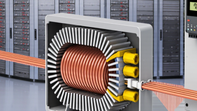
The core design should match the conductor and measurement purpose. A wound-primary transformer suits lower currents and controlled accuracy. A bar-primary design works well around busbars with high continuous current. Split-core models simplify retrofits, especially where cables cannot be disconnected. However, their convenience may bring lower accuracy or weaker mechanical protection. Check the ratio, rated burden, accuracy class, and saturation performance together. A perfect ratio is not enough.

Tips: Measure the cable space before ordering. Confirm the secondary terminal direction. Leave room for testing and maintenance. Never open a live secondary circuit. Use the latest applicable requirements, such as IEC 61869-2, with local electrical rules.

Insulation level depends on system voltage, lightning exposure, and installation environment. Do not select it from voltage alone. Review power-frequency withstand and lightning impulse withstand ratings. Outdoor installations need stronger protection against moisture, pollution, and ultraviolet exposure. Indoor switchboards may need less environmental protection, but tight clearances can create heat and access problems. Choose fixed installation for permanent, secure assemblies. Choose split-core installation when downtime must remain short. I have seen projects focus on installation speed and later struggle with cable bending space. That mistake is avoidable. Verify creepage, clearance, enclosure rating, grounding, and secondary wiring length before approval. Field conditions can defeat a technically correct datasheet.

Verify Safety, Compliance, Testing, and Long-Term Reliability

How to Choose a Current Transformer in 2026?

A current transformer must be selected for safety, compliance, testing, and service life. The IEA Electricity 2024 report expects global electricity demand to grow by about 4% annually through 2025. Higher network loading makes accurate measurement more important. Start with primary current, burden, frequency, insulation level, and fault withstand requirements. Small errors matter.

Check the design against IEC 61869-2 or the applicable national standard. Confirm the accuracy class at the actual burden, not only the catalog value. Protection CTs also need suitable knee-point performance and saturation margins.

Test before energizing. A qualified laboratory should verify ratio, polarity, insulation resistance, excitation characteristics, and accuracy.

Field acceptance testing should follow recognized practices, such as NETA ATS-2023, where applicable. Keep calibrated instruments and signed test records.

Long-term reliability depends on installation details.

Inspect terminal tightness, grounding, enclosure sealing, and cable routing.

Never leave a CT secondary open while the primary carries current. That mistake can create dangerous voltage.

Specify temperature, humidity, vibration, and corrosion exposure early. Review the maintenance plan with the operator, not just the purchaser.

I have seen technically correct selections fail because drawings omitted the shorting links. No checklist catches every field error.

Recheck assumptions after commissioning, especially when loads change or protection settings are revised.