Why Use a Current Transformer in Electrical Systems?
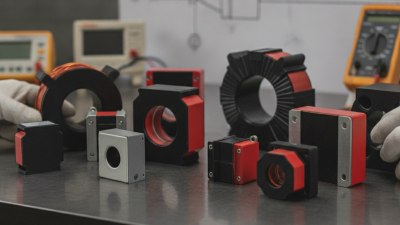
A Current Transformer helps electrical systems measure large currents without placing heavy current directly into instruments. It reduces primary current to a safer, standardized secondary value. That smaller signal can operate meters, relays, and monitoring equipment accurately.
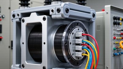
Power-system engineer and author C. R. Paul describes the purpose clearly: “A current transformer makes high current measurable, repeatable, and safer.” This principle remains visible in substations, factories, and commercial switchboards. A thick primary conductor may carry thousands of amperes. Meanwhile, a compact relay receives only a controlled secondary current. The arrangement protects sensitive equipment and supports dependable fault detection.
Safety matters, but accuracy matters just as much. Incorrect ratio selection can distort readings during overloads. Poor wiring can also create dangerous secondary voltages when the circuit is open. Small details matter.
Engineers select a Current Transformer according to ratio, burden, accuracy class, insulation level, and protection requirements. Metering transformers prioritize precision near normal operating loads. Protection transformers must remain reliable during severe fault currents. These needs can conflict. A design that appears economical may perform poorly under real fault conditions.
Field experience also exposes an uncomfortable truth: installation quality often limits transformer performance. Loose terminals, incorrect polarity, and neglected testing can undermine a sound design. Regular inspection, burden verification, and insulation testing reduce those risks. Yet no transformer is perfect. Temperature, saturation, aging, and manufacturing variation still influence results.
Understanding these limitations helps engineers use current transformers responsibly. The goal is not merely to measure electricity. It is to create trustworthy information for safer decisions, faster protection, and more stable electrical operation.
Why Use a Current Transformer in Electrical Systems?
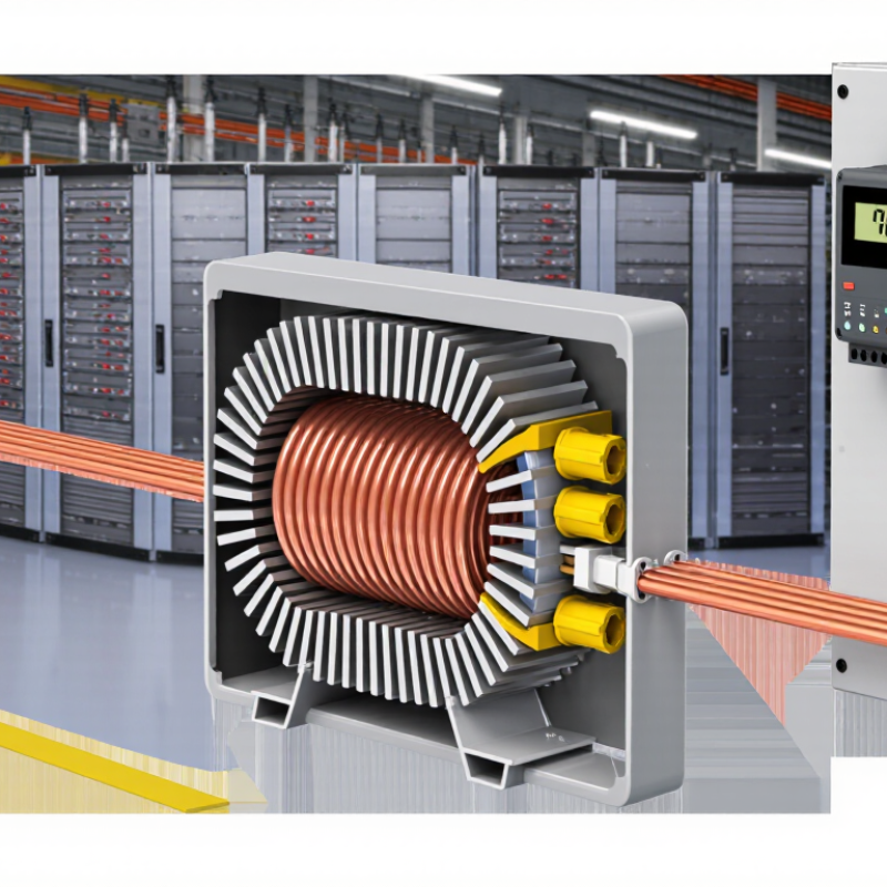
A current transformer measures large alternating currents safely and accurately. It reduces primary current to a smaller, standardized secondary value. The primary conductor passes through a magnetic core. Its changing magnetic field induces current in the secondary winding. This output feeds meters, protective relays, and monitoring equipment. Electrical isolation also protects low-voltage instruments from high-energy circuits.
The current ratio defines the measurement. A 1,000:5 CT should produce 5 amperes when primary current reaches 1,000 amperes. However, the tidy textbook ratio is never perfectly tidy. Core saturation, temperature, wiring resistance, and excessive burden create errors. IEC 61869-2 addresses key requirements for measuring current transformers. The IEA’s Electricity 2024 report forecasts global electricity demand to rise by about 3.4% annually through 2026. More generation and distribution equipment means more dependable current measurement. Accurate data supports safer switching and faster fault detection.
Tips: Select the ratio from expected operating load, not only the maximum fault current. Confirm accuracy class and burden before installation. Never leave an energized CT secondary open-circuit; dangerous voltage can develop. A commissioning check should compare phase readings under load. It may reveal reversed polarity or loose terminals. Small mistakes matter.
Why Use a Current Transformer in Electrical Systems?
Why Electrical Systems Need Current Measurement
Electrical systems need current measurement to operate safely and predictably. A current transformer, or CT, reduces large primary currents to measurable secondary values. This allows meters and protective relays to monitor equipment without carrying the full line current. The separation also improves operator safety during testing and routine inspection.
Current readings reveal changing conditions inside a system. A sudden increase may indicate overload, a damaged motor, or a developing short circuit. Uneven readings between phases can suggest poor connections or unbalanced loads. In a plant, an engineer might compare a motor’s measured current with its rated value while checking vibration and temperature. That combination gives better evidence than one reading alone.
Small details matter. The CT ratio must match the expected load range, or readings may become inaccurate. Its burden rating, wiring length, and installation direction also affect performance. Never leave a CT secondary open while current flows through the primary. Dangerous voltage can develop. Qualified personnel should follow applicable electrical standards and verify the circuit before maintenance.
A common mistake is treating current measurement as a perfect answer. It is not. A stable current reading can hide insulation problems, mechanical wear, or intermittent faults. Regular measurements, accurate records, and practical inspection provide stronger evidence. Some installations also need power quality analysis, especially when nonlinear equipment creates distorted waveforms.
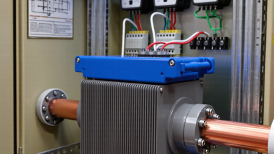
A current transformer (CT) separates high-power conductors from measuring and protection circuits. Its core converts a primary current into a safer secondary value, commonly 1 A or 5 A. This allows meters and relays to operate inside a control cabinet, away from exposed busbars.
The isolation matters when a feeder carries hundreds or thousands of amperes. A technician can inspect a protected test terminal instead of approaching the energized conductor. NFPA 70E (2024) emphasizes establishing electrically safe work conditions and controlling shock and arc-flash risks. ESFI’s analysis of U.S. Bureau of Labor Statistics data recorded 126 workplace electrical fatalities in 2022. A CT cannot remove every hazard, but it can reduce direct exposure during measurement.
A practical installation includes shorting terminals, correct grounding, and clearly marked secondary wiring. Never leave an energized CT secondary open. High voltage can develop across the terminals, even when the primary circuit looks ordinary. IEC 61869-2 also links CT performance to accuracy, burden, and protection requirements. A poorly matched burden can distort readings or delay relay operation. That detail is often missed. The design is not foolproof. Loose terminals, incorrect polarity, or an underrated insulation system can still create danger. In real panels, a small label and a secure test block may prevent a serious mistake.
A 1000:5 current transformer reduces high primary currents to a standardized 0–5 A secondary signal for meters and protective relays. This provides galvanic isolation between high-voltage conductors and low-voltage measurement equipment, improving operator safety and simplifying instrumentation. The secondary circuit must never be left open while the primary is energized.
Why Use a Current Transformer in Electrical Systems?
Using Current Transformers for Protection and Control
A current transformer, or CT, converts high primary current into a safer, measurable secondary signal. Protection relays use this signal to detect overloads, short circuits, and earth faults. Control systems use it to balance loads, monitor feeders, and adjust operating limits. The need is growing. The International Energy Agency reported that global electricity demand increased by about 2.2% in 2023 and expects stronger growth through 2026. More power flows require clearer measurements.
For reliable protection, CT accuracy matters during both normal load and severe faults. IEC 61869-2 defines key requirements for instrument transformers, including accuracy classes and saturation performance. A saturated CT may understate fault current. That delay can leave cables, transformers, or switchgear exposed. The North American Electric Reliability Corporation’s 2024 reliability assessment continues to identify protection-system performance as an important reliability concern. Field testing also reveals practical issues. Loose terminals, incorrect polarity, and excessive cable burden can defeat a well-designed scheme. I have seen commissioning teams discover these problems only after secondary injection testing. That is an uncomfortable lesson.
Tips: Select the CT ratio from measured load data, not guesswork. Check the knee-point voltage for high-impedance protection. Confirm polarity before energizing. Record test results and review them after major load changes. A perfect calculation can still fail in a dirty panel or poorly tightened terminal.
| Application Area | Current Transformer Function | Typical Secondary Current | Common Accuracy Requirement | Key Protection or Control Benefit | Important Selection Considerations |
|---|---|---|---|---|---|
| Overcurrent Protection | Reduces high primary current to a standardized, measurable secondary current for protective relays. | 1 A or 5 A | Protection class such as 5P10 or 10P20, depending on the protection design. | Allows the relay to detect overloads and short-circuit conditions without connecting directly to the high-current conductor. | Check the rated accuracy limit factor, burden, fault-current level, and protection coordination requirements. |
| Differential Protection | Supplies current measurements from multiple sides of a transformer, generator, motor, or busbar zone. | 1 A or 5 A | Protection performance must be suitable for differential schemes; PX-class characteristics may be required for some designs. | Enables comparison of currents entering and leaving a protected zone to identify internal faults. | Matching ratio, polarity, saturation behavior, excitation characteristics, and lead resistance are critical. |
| Earth-Fault Protection | Measures residual or zero-sequence current caused by current flowing from the circuit to earth. | 1 A or 5 A; sensitive designs may use a dedicated core or core-balance CT. | Selected according to the relay sensitivity and the expected earth-fault current range. | Improves detection of insulation failures and leakage paths that may not produce large phase overcurrents. | Consider residual-current measurement method, conductor arrangement, minimum pickup current, and external magnetic fields. |
| Metering and Energy Measurement | Provides an isolated current signal for ammeters, power meters, energy meters, and monitoring systems. | Commonly 1 A or 5 A | Typical metering classes include 0.2S, 0.5S, and 1.0, depending on the measurement system. | Enables accurate measurement while electrically isolating instruments from the primary circuit. | Specify ratio, rated burden, phase displacement, accuracy over the operating-current range, and sealing requirements where applicable. |
| Motor Protection and Control | Feeds motor-protection relays and control systems with scaled phase-current information. | 1 A or 5 A | Usually a protection class selected for overload, locked-rotor, short-circuit, and unbalance functions. | Supports thermal modeling, overload protection, phase-loss detection, and abnormal-current alarms. | Account for motor starting current, transient performance, CT saturation, and the relay input specification. |
| Generator Protection | Measures generator phase currents for stator, negative-sequence, reverse-power, and differential protection. | 1 A or 5 A | Protection class and transient performance must match the generator protection scheme. | Provides essential current feedback for detecting internal faults and abnormal operating conditions. | Evaluate subtransient fault current, remanence, saturation, grounding method, and CT placement. |
| Busbar Protection | Collects current signals from all circuits connected to a busbar protection zone. | 1 A or 5 A | High-performance protection CTs are commonly required to maintain stability during external faults. | Allows rapid discrimination between internal busbar faults and faults outside the protected zone. | Use compatible ratios and polarity; verify saturation limits, wiring burden, and the complete stability calculation. |
| Power Quality and Monitoring | Provides isolated current signals to monitoring equipment for load trends, harmonics, and abnormal conditions. | 1 A, 5 A, or a sensor-specific low-level output | Accuracy depends on the monitoring equipment and the required measurement bandwidth. | Supports load management, preventive maintenance, demand analysis, and condition monitoring. | Check frequency response, harmonic performance, phase error, installation space, and compatibility with the monitoring input. |
| Isolation and Safety | Provides galvanic separation between high-voltage primary conductors and low-voltage instruments or relays. | Typically 1 A or 5 A on conventional secondary circuits | Insulation and dielectric requirements are specified separately from measurement accuracy. | Reduces the voltage exposure of connected equipment and makes measurement systems practical in high-current circuits. | Never leave a conventional CT secondary open while primary current is flowing; use a shorting terminal or approved test switch. |
| Control and Automation | Converts primary current into a signal used by controllers, protection devices, and automated switching systems. | 1 A or 5 A for conventional CTs; other outputs may be used by electronic sensors. | Must meet the input accuracy and signal requirements of the connected controller or relay. | Enables automatic load shedding, feeder control, interlocking, alarms, and closed-loop operating functions. | Confirm signal compatibility, response time, burden, wiring length, electromagnetic environment, and fail-safe behavior. |
| Common Ratio Selection | Defines the relationship between primary current and secondary current. | Examples: 100/5 A, 400/5 A, 800/1 A | The ratio should support the required accuracy at normal load and adequate performance during faults. | Ensures that measuring and protection devices receive a usable signal across the expected operating range. | Choose a ratio close to the normal maximum load without exceeding the CT thermal, insulation, or short-time ratings. |
| Burden and Wiring | Supplies current through the connected relay, meter, terminals, and secondary wiring. | Specified in volt-amperes, commonly according to the CT design and installation. | The connected burden must not exceed the CT rated burden if the specified accuracy is to be maintained. | Correct burden selection helps prevent excessive ratio error and premature saturation. | Include instrument impedance, terminal resistance, cable length, conductor size, and temperature effects in the calculation. |
| Saturation Management | Maintains usable secondary current during high primary fault currents. | Depends on the CT core, ratio, burden, and fault-current waveform. | Protection CTs require suitable accuracy-limit performance; metering CTs may be designed to limit secondary current under faults. | Improves relay dependability for internal faults and stability for external faults. | Assess DC offset, remanent flux, fault duration, burden, and the required relay operating time. |
A current transformer safely converts high line current into a measurable secondary signal. This supports protection, metering, and equipment monitoring without exposing instruments to primary voltage. Selection begins with the system’s maximum continuous current, fault level, and operating voltage. A ratio that is too high reduces measurement resolution. A ratio that is too low can saturate during heavy faults. This small mismatch can distort protection decisions.
Accuracy class matters as much as ratio. Metering applications often require low errors near normal load, while protection circuits must remain reliable during fault currents. IEC 61869-2 defines performance requirements for measuring transformers, including accuracy and saturation behavior. The International Energy Agency’s Electricity 2024 report expects global electricity demand to grow by nearly 6% through 2026. More variable generation and heavier network loading make dependable current measurement increasingly important.
Check the secondary burden, insulation level, frequency, and installation space. A long cable run adds burden and can reduce accuracy. Open-circuiting a CT secondary is dangerous because high voltage may develop. Use suitable shorting terminals and follow qualified maintenance procedures. In field work, I would also compare the expected load profile with the nameplate rating, not only the maximum value. That step is easy to miss. Temperature, harmonics, and aging can change real performance. The best selection is not always the largest transformer; it is the one matched to actual operating conditions and verified test data.