



![SC[B]-10 Dry Type Transformer](/source/dc90e9d39dd0711afae47155707cd0e5/sc-b-10-dry-type-transformer_thumbW360.jpg)
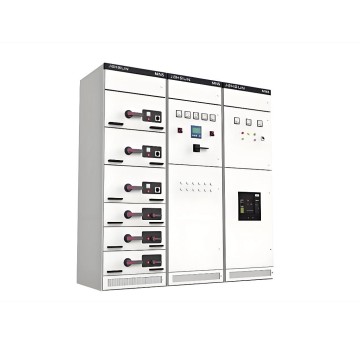
01
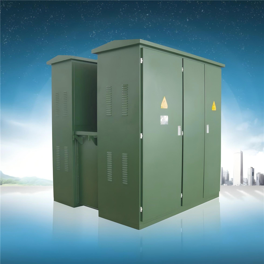
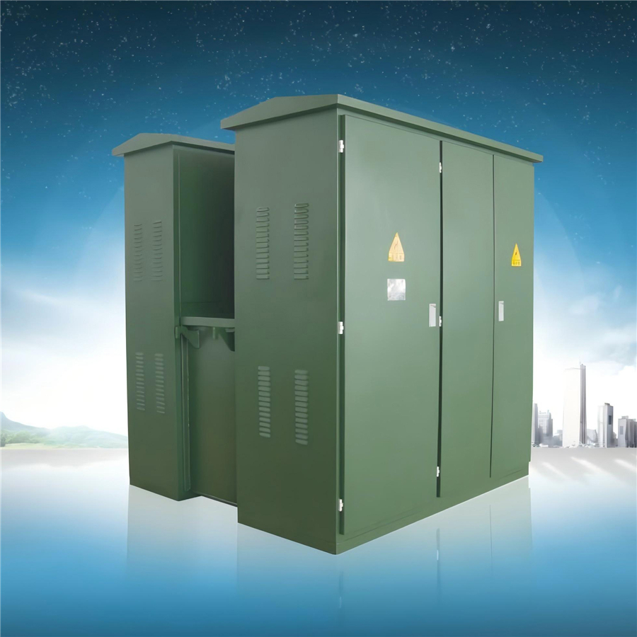
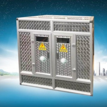
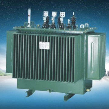
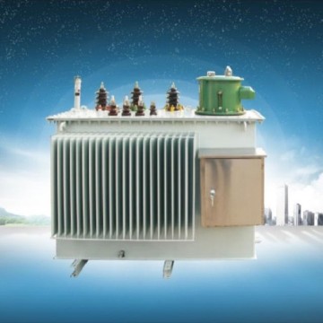
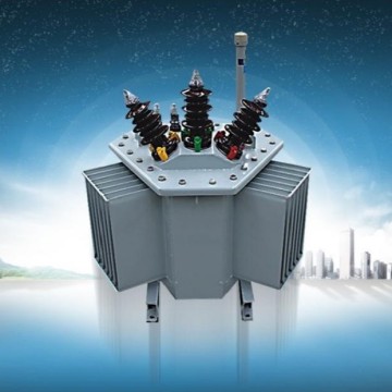
ZGS13 Modular Substations(American Style)
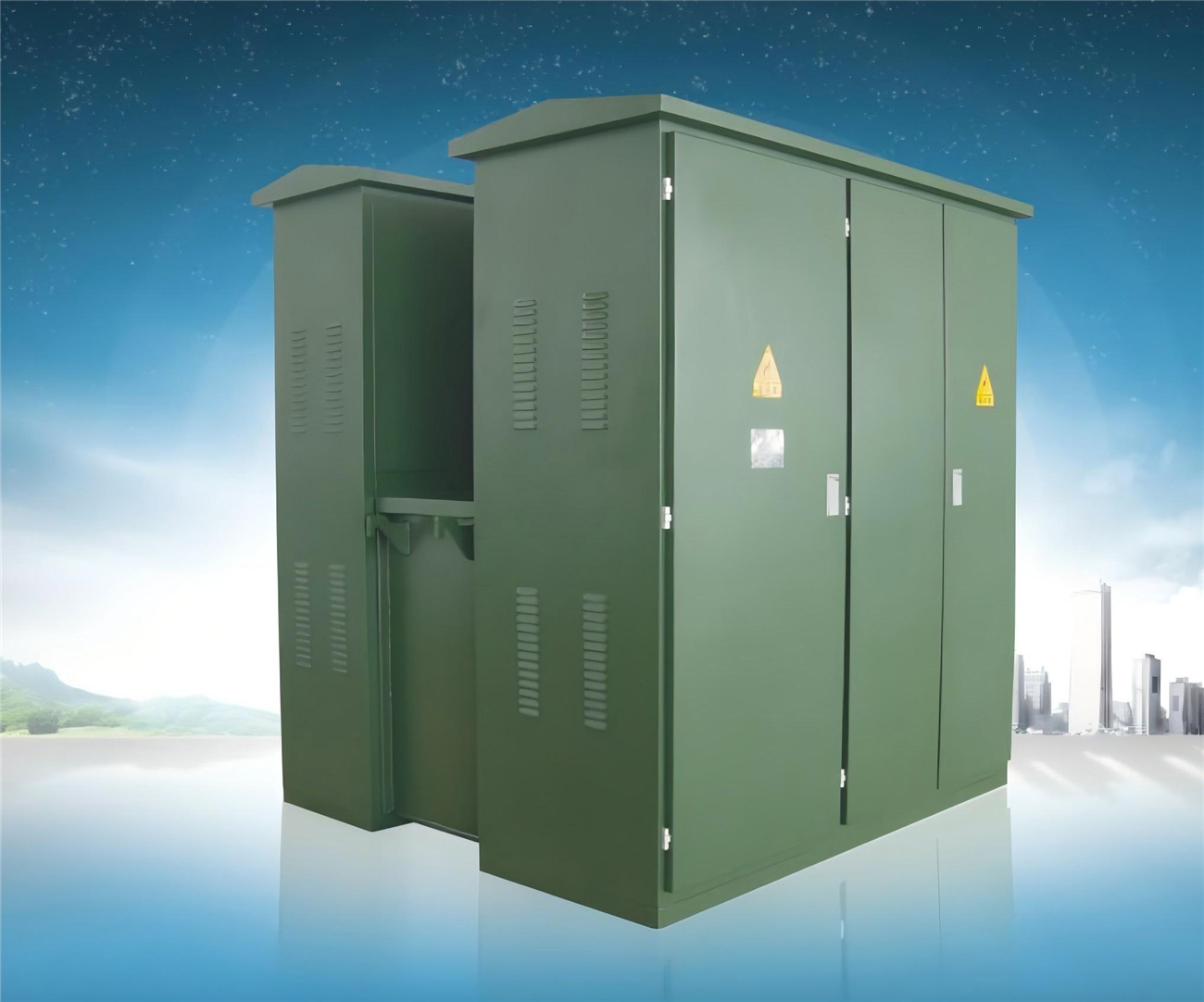
Product overview
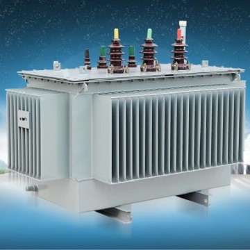
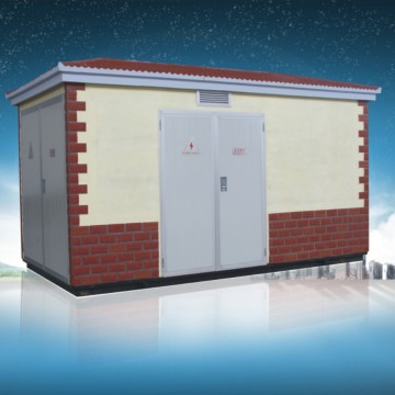
ZGS modular substations(American style)are designed for use as high voltage distribution metering,compensation control andprotection devices in 7.2kV and 12KV loop power,dual power supply or terminal power supply systems.In addition to the transformerinstalled in the combined substation,the high-voltage side is also equipped with four-position load switch,two-station load switch,backupprotection fuse and plug-in fuse low-voltage side according to the requirements of the user assembly control appliances,distributionappliances,compensation devices and power meters.
ZBW(ZGS)modular substation (American style)can be used in indoor and outdoor,widely used in industrial parks,residential districts,commercial centers and high-rise buildings and other places.
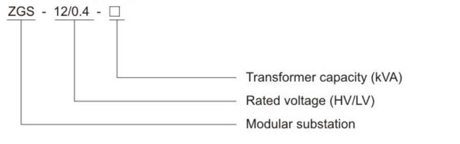
Model meaning
Using the environment
1.Altitude:1000m and below;
2.Wind pressure:no more than 70Pa(equivalent to 35m/s);
3.Humidity:the daily average is no more than 90%,and the monthly average is no more than 90%;
4.Ambient temperature:maximum temperature +40℃,minimum temperature -25℃;
5.Shockproof level:horizontal acceleration 0.4/S2;Vertical acceleration 0.15m/s2;
6.earthquake intensity:8 degrees;
7.Instllation environment:the surrounding ai i free from obvious pollution such as corrosive,flammable gas and water vapor,and theinstallation site is free from violent vibration.
Functional Characteristics
1.Small volume,compact structure,only about 1/3 of the same capacity box in China;
2.Fully sealed,fully insulated,no insulation distance required,reliable guarantee of personal safety;
3.It can be used in both ring network and terminal,which is very convenient for conversion and improves the reliability of power supply;
4.Low loss,lower than the loss of domestic S9 transformer;
5.the cable connector can operate 200A load curent,in emergency can be used as a load switch operation,and has the characteristics ofisolation switch;
6.Double fuse protection is adopted to reduce the operating cost.The insert fuse is a double-sensitive fuse (temperature,current);
7.△/Ywas adopted.The advantages of connection method and three-phase five-column structure are high voltage quality,no drift of neutralpoint,no heating of box body,low noise and good lightning protection.
Technical parameters table of composite substation
| No. | Items | Units | Data |
| 1 | Rated voltage | kV | 10/0.4(High voltage/low voltage) |
| 2 | Maximum operating voltage | kV | 12(High voltage side) |
| 3 | Rated frequency | Hz | 50 |
| 4 | Nominal capacity | kVA | 50-1600 |
| 5 | 1minute power frequency withstand voltage | kV | 35 |
| 6 | Lightning impulse voltage | kV | 75 |
| 7 | Cooling way | Oil-immersed self-cooling | |
| 8 | The hV backup fuse switches off the current | kA | 50 |
| 9 | The plug-in fuse switches off the current | kA | 2.5 |
| 10 | The environment temperature | -35-+40 | |
| 11 | The coil allows temperature to rise | 65 | |
| 12 | No load voltage regulation | ±5%or±2×2.5% | |
| 13 | Noise level | db | 50 |
| 14 | Protection grade | IP43 |
Technical parameters of transformer
The new Type S9 series transformer body is selected,with low loss,good overload capacity and strong short-circuit resistance. Al fasteners are treated with anti-loose and free of hanging core.S10 series and S11 series transformers with better performance can also be selected.
| Capacity KVA | Voltage(kV) | Join group label | No-load current % | No-load loss(KW) | Impedance voltage% | Load loss(KW) | |||||||
| HV | LV | S9 | S10 | S11 | S9 | S10 | S11 | S9 | S10 | S11 | |||
| 50 | 10±5% or ±2×2.5% | 0.4 | Dyn11 or Yyno | 2.0 | 1.9 | 0.75 | 0.17 | 0.15 | 0.12 | 4.0 | 0.87 | 0.83 | 0.87 |
| 63 | 1.9 | 1.8 | 0.7 | 0.2 | 0.18 | 0.14 | 1.04 | 0.99 | 104 | ||||
| 80 | 1.9 | 1.7 | 0.7 | 0.25 | 0.22 | 0.175 | 1.25 | 1.2 | 125 | ||||
| 100 | 1.8 | 1.55 | 0.65 | 0.29 | 0.26 | 0.2 | 1.5 | 1.42 | 1.5 | ||||
| 125 | 1.7 | 1.45 | 0.65 | 0.34 | 0.3 | 0.235 | 1.8 | 1.72 | 1.8 | ||||
| 160 | 1.6 | 1.3 | 0.6 | 0.4 | 0.36 | 0.27 | 2.2 | 2.12 | 2.2 | ||||
| 200 | 1.5 | 1.2 | 0.55 | 0.48 | 0.43 | 0.33 | 2.6 | 2.5 | 2.6 | ||||
| 250 | 1.4 | 1.1 | 0.5 | 0.56 | 0.5 | 0.39 | 3.05 | 2.9 | 3.05 | ||||
| 315 | 1.4 | 1.0 | 0.45 | 0.67 | 0.29 | 0.465 | 3.65 | 3.45 | 3.65 | ||||
| 400 | 1.3 | 1.0 | 0.4 | 0.8 | 0.71 | 0.56 | 4.3 | 4.15 | 4.3 | ||||
| 500 | 1.2 | 1.0 | 0.4 | 0.96 | 0.85 | 0.67 | 5.15 | 4.82 | 5.15 | ||||
| 630 | 1.1 | 0.8 | 0.4 | 1.2 | 1.6 | 0.81 | 4.5 | 6.2 | 5.86 | 6.2 | |||
| 800 | 1.0 | 0.7 | 0.35 | 1.4 | 1.23 | 0.98 | 7.5 | 7.2 | 7.5 | ||||
| 1000 | 1.0 | 0.6 | 0.3 | 1.7 | 1.5 | 1.15 | 10.3 | 9.8 | 10.3 | ||||
| 1250 | 0.9 | 0.6 | 0.27 | 1.95 | 1.72 | 1.36 | 12.0 | 12.2 | 12.0 | ||||